How Contact Force Stability Impacts EMI Shielding Effectiveness
Our EMI shielding gaskets are engineered for applications where contact force stability is critical to long-term electromagnetic compatibility. Unlike conventional gaskets that lose compression over time due to stress relaxation, thermal cycling, or vibration, our solutions maintain consistent contact force throughout the product lifecycle.
Key advantages:
-
Stable shielding performance: Minimal force relaxation ensures sustained low contact resistance
-
Multiple force classes: Low, moderate, and standard force options to match your application requirements
-
Proven durability: Tested for force retention under heat aging, thermal cycling, and vibration
-
Optimized designs: Metallic spring gaskets and spring-energized elastomeric options for demanding environments
Ideal for aerospace, military, industrial electronics, and telecom applications where reliable EMI protection is non-negotiable. Available with groove design support and performance validation data.
In the world of electromagnetic interference (EMI) shielding, the performance of a gasket is often judged by its material conductivity, shielding effectiveness ratings, and environmental durability. Yet there is one critical factor that engineers sometimes overlook—contact force stability.
A shielding gasket that loses its compressive force over time will inevitably compromise the very protection it was designed to provide. This article explores why contact force stability matters, how it affects shielding performance, and what design considerations ensure long-term reliability.
Why Contact Force Matters in EMI Shielding
EMI shielding gaskets function by creating a continuous conductive path between two mating surfaces—typically a enclosure door and its frame, or two housing components. This conductive path completes a Faraday cage, preventing electromagnetic waves from entering or escaping the protected space.
For this conductive path to be effective, the gasket must maintain consistent electrical contact across its entire length. Any gap, gap, or high-resistance point can become an antenna or leakage path, drastically reducing shielding effectiveness.
The Role of Contact Force
Contact force is the compressive pressure that the gasket exerts against the mating surfaces. This force serves two essential purposes:
- Ensures low-resistance contact: Higher force typically reduces contact resistance by increasing the number of contact points and breaking through thin surface oxides.
- Maintains contact over time: Environmental factors such as vibration, thermal cycling, and material creep can cause gaps to form if the gasket lacks sufficient or stable contact force.
The relationship between contact force and shielding effectiveness is not linear. A gasket with insufficient force will exhibit rapidly declining shielding performance as even minor gaps appear. Conversely, excessive force may damage the gasket, housing, or fasteners, or create assembly challenges.
The Physics of Contact Resistance
The fundamental relationship governing EMI shielding effectiveness is contact resistance. When two conductive surfaces meet, the actual contact occurs only at microscopic asperities—the high points on each surface. The total contact area is a fraction of the apparent area.
Contact resistance is determined by three factors:
- Number of contact points: More points mean lower resistance.
- Contact force: Higher force deforms asperities, creating more contact points.
- Surface condition: Oxides, contaminants, and surface roughness increase resistance.
As contact force decreases, the number of active contact points diminishes. When force falls below a threshold, the remaining contact points cannot carry the required current, and the interface becomes a source of electromagnetic leakage.
How Force Instability Develops
Even a well-designed shielding system can lose contact force over time. Understanding how force instability develops is essential for selecting robust solutions.
1. Material Relaxation (Stress Relaxation & Creep)
All elastomeric and metallic materials experience some degree of stress relaxation over time—a gradual reduction in force under constant compression. This is particularly pronounced in:
- Elastomeric gaskets: Conductive silicone or fluorosilicone gaskets can lose 15–30% of their initial force over time, especially at elevated temperatures.
- Metallic gaskets: While more stable, some metallic materials (such as certain aluminum alloys) may also creep under sustained compression.
2. Thermal Cycling
Temperature variations cause differential expansion between the gasket, housing, and fasteners. Repeated thermal cycles can:
- Accelerate stress relaxation
- Loosen fasteners
- Create permanent deformation in gasket materials
3. Vibration and Mechanical Shock
In applications such as aerospace, automotive, or industrial equipment, vibration can gradually reduce contact force through:
- Fastener loosening
- Microscopic fretting wear on contact surfaces
- Gradual settling of the gasket into the groove
4. Improper Groove Design
A groove that is too deep, too shallow, or incorrectly sized can cause the gasket to be either under-compressed (insufficient force) or over-compressed (accelerated relaxation). Both scenarios lead to premature loss of contact force.
5. Tolerances Stack-Up
Manufacturing tolerances on mating components can result in actual compression varying significantly from the design intent. A stack-up of tolerances may leave the gasket with less than the required compression, or in some cases, with excessive compression that accelerates material fatigue.
The Shielding Effectiveness Curve: A Visual Representation
The relationship between contact force and shielding effectiveness can be conceptualized as having three distinct regions:
| Compression Range | Force Level | Shielding Effectiveness | Risk |
|---|---|---|---|
| Under-compressed | Below optimal | Poor to moderate | High risk of gaps and leakage |
| Optimal range | Recommended force | Optimal (design rating) | Stable performance |
| Over-compressed | Excessive force | Good initially, but declining over time | Accelerated relaxation, possible gasket damage |
Why the over-compressed zone is dangerous: While initial shielding may be excellent, excessive compression accelerates stress relaxation. Over time, the gasket may actually end up under-compressed—with worse performance than if it had been correctly compressed from the start.
Measuring Contact Force Stability
Quantifying contact force stability requires both static and dynamic considerations:
Static Contact Force
The initial compression force should fall within the manufacturer’s recommended range—typically 15% to 30% of the gasket’s original height for elastomeric types, or a specific compression percentage for metallic spring gaskets.
Force Retention
Force retention is the percentage of initial force maintained after exposure to environmental stresses. High-quality gaskets maintain at least 70–80% of initial force after accelerated aging tests such as:
- Heat aging: 70°C to 100°C for 7 to 30 days
- Thermal cycling: Multiple cycles between extreme temperatures
- Humidity exposure: 85% relative humidity at elevated temperatures
Engineering Solutions for Stable Contact Force
Selecting gaskets with stable contact force requires understanding the application environment and choosing appropriate technologies.
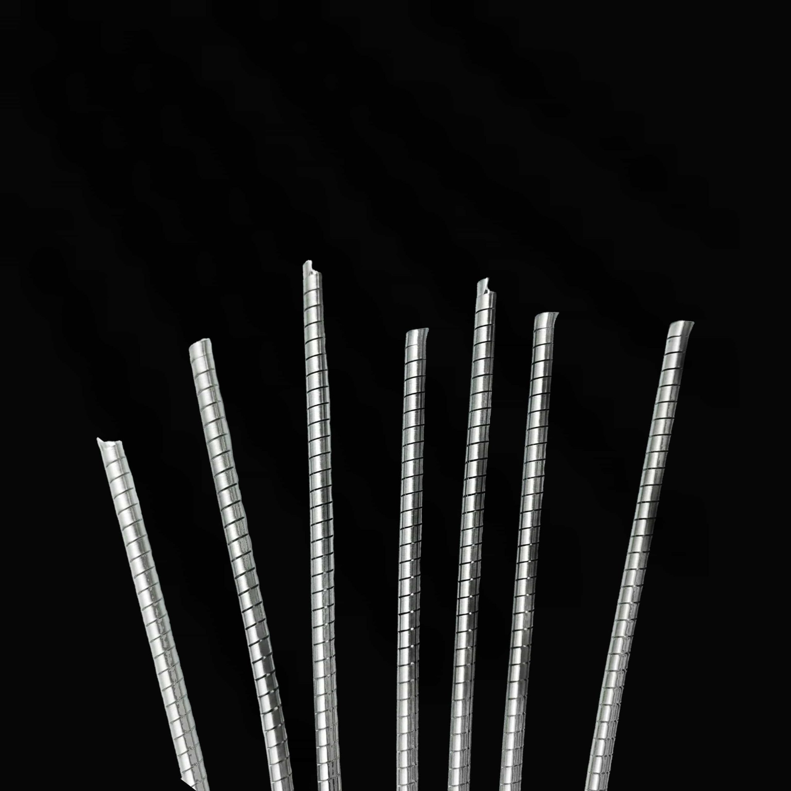
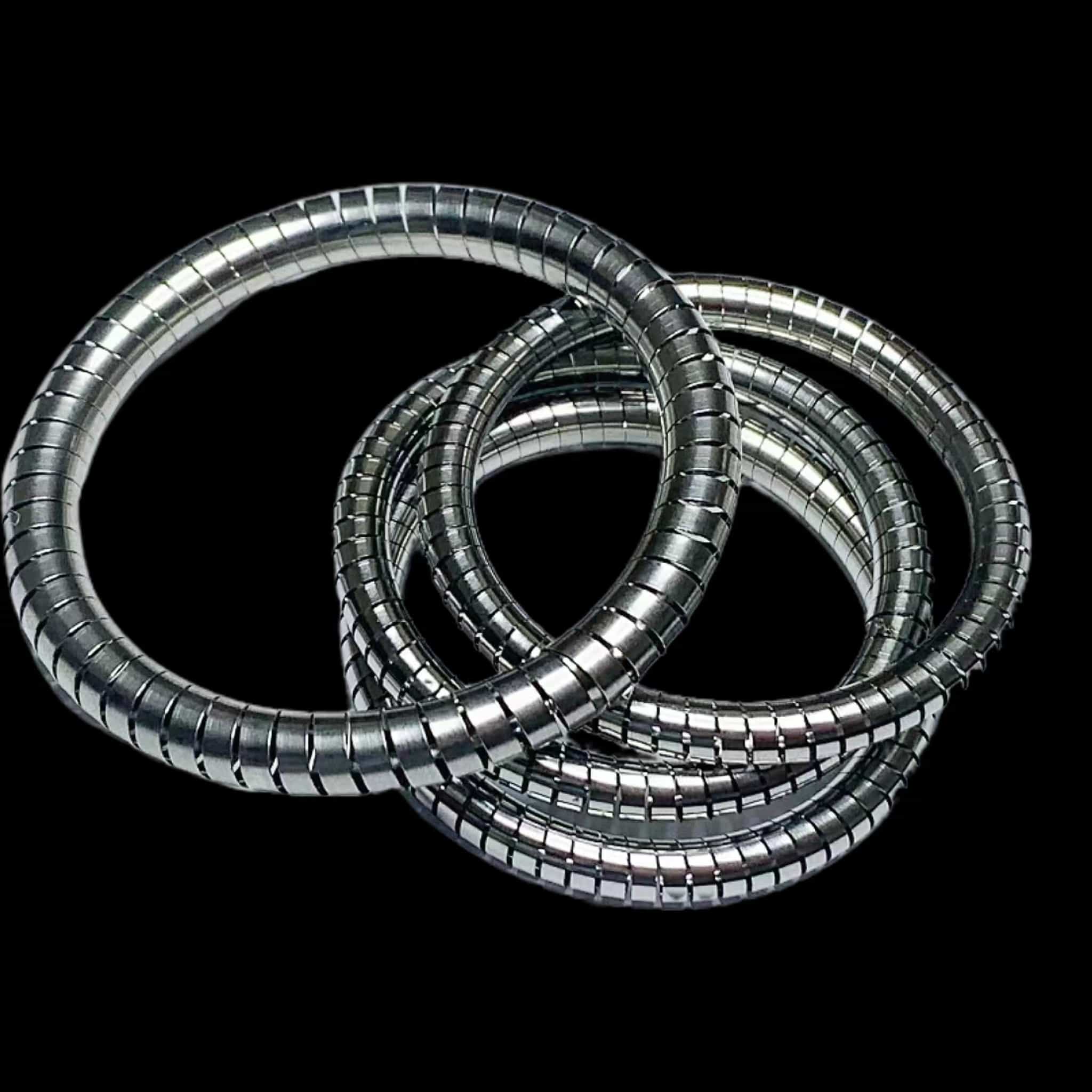
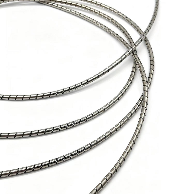
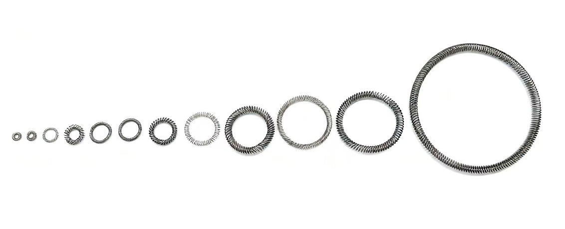
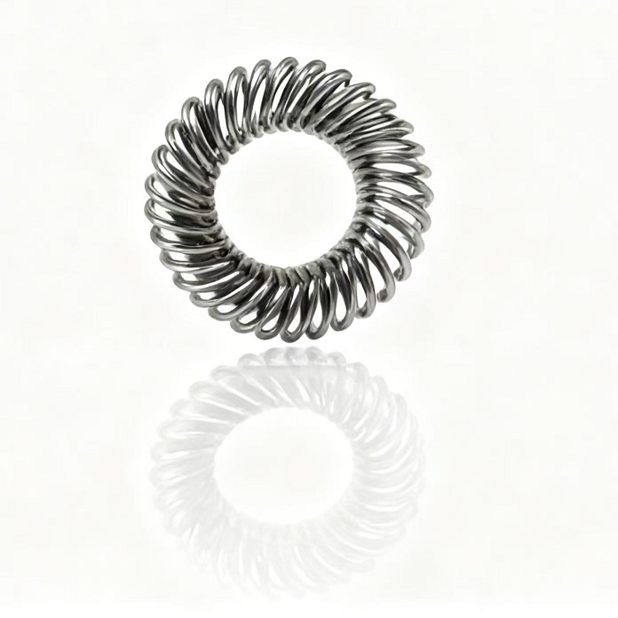
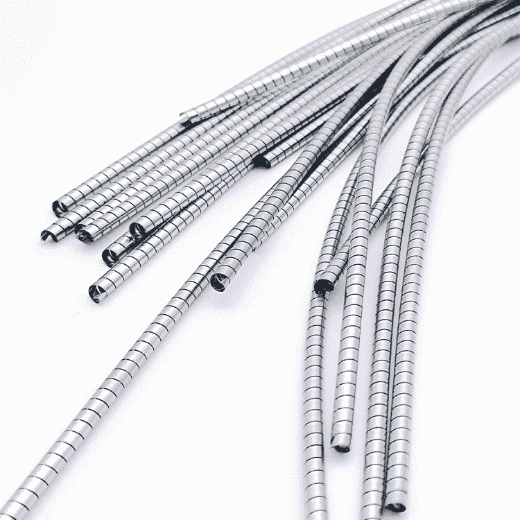
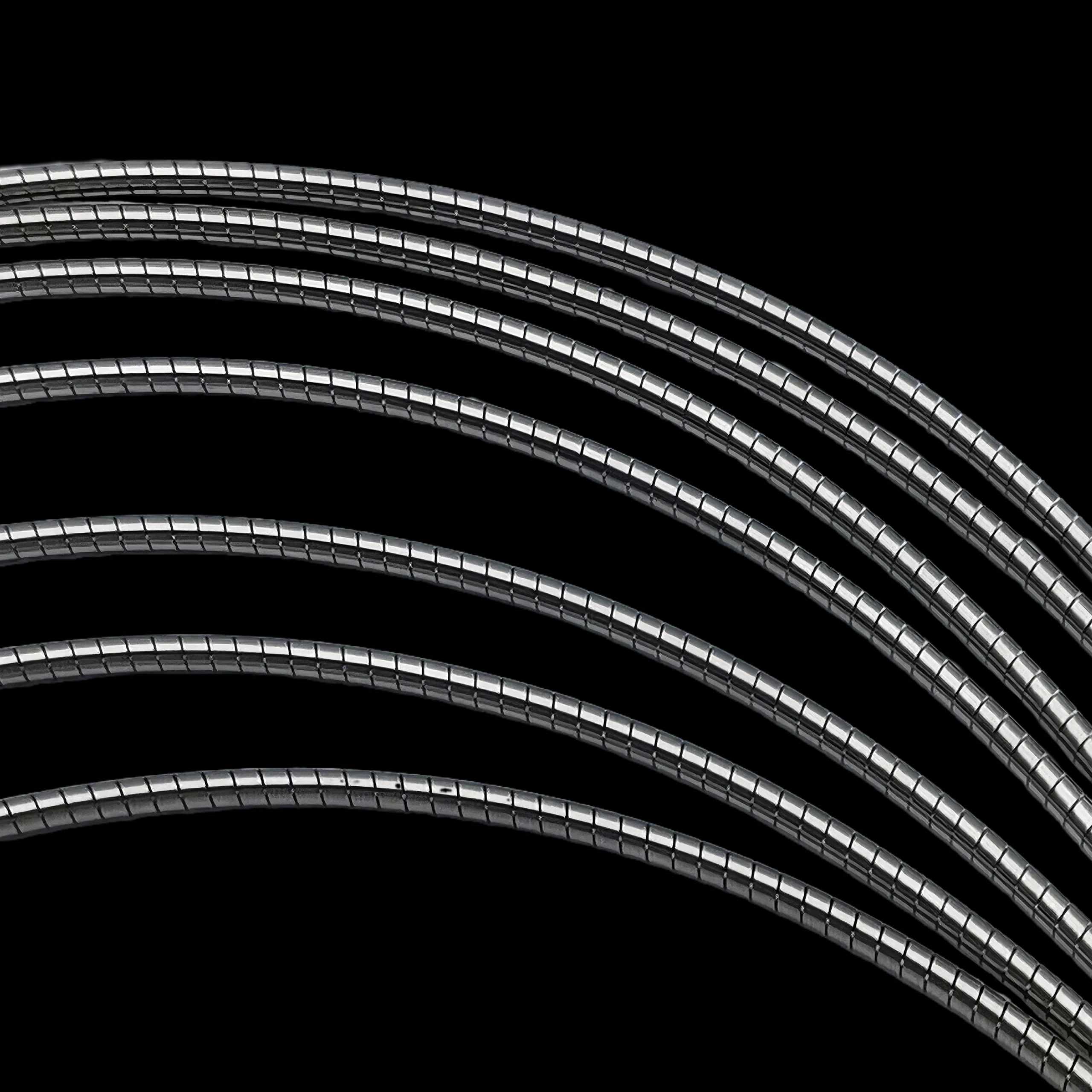
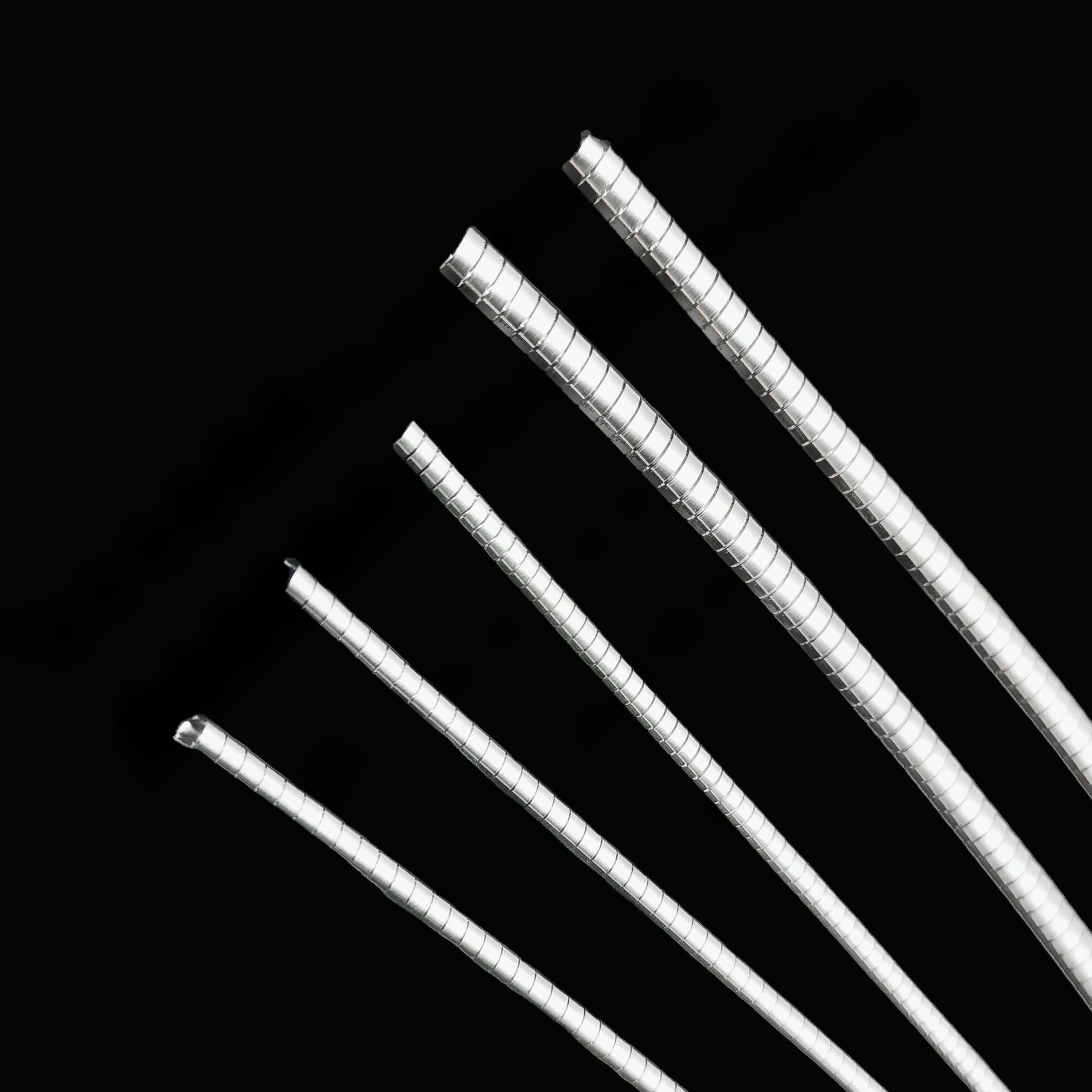
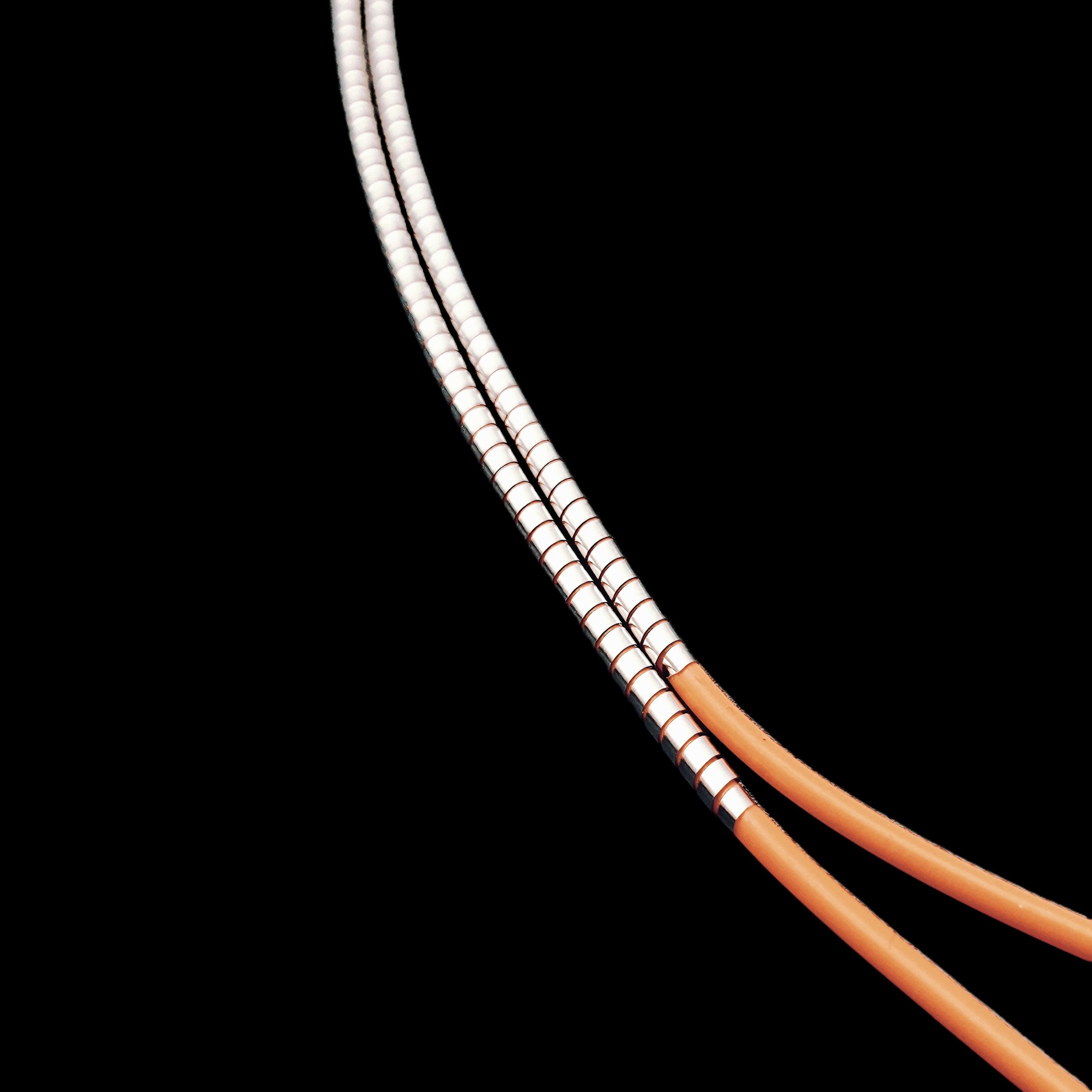
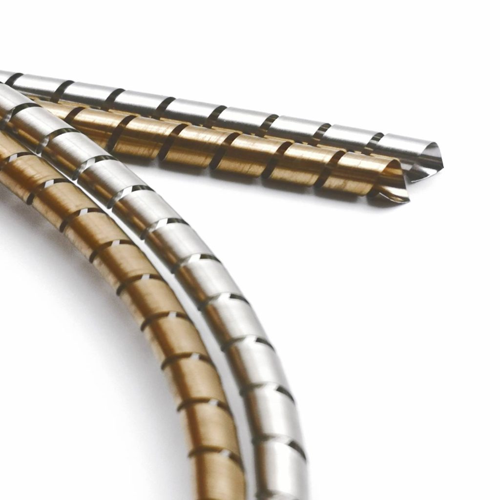
1. Metallic Spring Gaskets
Spiral-wound, canted coil, or finger stock gaskets offer superior force stability compared to elastomeric alternatives. Their metal-on-metal contact provides:
- Minimal stress relaxation (typically <5% over life)
- Stable performance across wide temperature ranges
- Resistance to outgassing and chemical attack
However, metallic gaskets generally require higher compression forces and may have higher installed costs.
2. Elastomeric Gaskets with Spring Cores
For applications requiring environmental sealing combined with EMI shielding, elastomeric gaskets with internal spring cores provide a balance. The spring maintains contact force even if the elastomer relaxes.
3. Optimized Groove Design
Regardless of gasket type, proper groove dimensions are essential. Key design parameters include:
- Groove depth: Should be slightly less than the gasket height (typically 70–85% of gasket height)
- Groove width: Sufficient to contain the gasket without causing excessive side compression
- Surface finish: Smooth enough to prevent wear, but not so smooth that the gasket cannot grip
4. Force Classification Selection
Many EMI gasket manufacturers offer multiple force classes:
| Force Class | Relative Force | Typical Applications |
|---|---|---|
| Low Force | ~1.5 lb/in | Plastic housings, lightweight structures |
| Moderate Force | ~10 lb/in | General industrial, standard enclosures |
| Standard Force | ~30 lb/in | High reliability, military, aerospace |
Selecting the appropriate force class for the application is critical—too low, and contact stability may be compromised; too high, and assembly challenges may arise.
Real-World Impact: A Case Study
Consider two identical electronic enclosures, both specified with a moderate-force EMI gasket achieving 100 dB shielding effectiveness in laboratory tests.
Enclosure A: The groove is correctly designed with 25% compression. The gasket remains within its optimal range throughout thermal and vibration testing. Final shielding effectiveness: 98 dB.
Enclosure B: The groove is 0.010 inches deeper than specified due to machining tolerances. Initial compression is only 18%, still within range. However, after 100 thermal cycles and vibration testing, the gasket relaxes to 14% compression—below the minimum recommended. Shielding effectiveness drops to 65 dB, causing a compliance failure.
The difference between the two was not the gasket itself, but the stability of the contact force throughout the product’s expected operating life.
Selecting for Contact Force Stability
When evaluating EMI shielding gaskets for a new design, consider these factors:
1. Application Environment
- Temperature extremes: Select materials rated for the full operating range.
- Thermal cycling frequency: Frequent cycles require materials with low relaxation.
- Vibration exposure: Consider gaskets with mechanical retention features if needed.
2. Compression Management
- Specify tolerance control: Define allowable groove depth and mating surface variation.
- Consider force vs. deflection curves: Ensure the operating point lies in the flattest region of the curve for maximum stability.
3. Lifecycle Requirements
- Expected service life: Longer life demands materials with proven long-term relaxation data.
- Maintenance access: If the gasket will be compressed and released repeatedly, consider materials with excellent recovery.
4. Testing and Validation
- Require force retention data: Request test reports showing compression force retention after environmental exposure.
- Conduct life testing: If possible, validate with representative thermal and vibration profiles.
Conclusion
Contact force stability is not a secondary consideration in EMI shielding—it is a primary determinant of long-term performance. A gasket that achieves excellent shielding in initial tests but loses contact force over time will inevitably fail to protect the sensitive electronics it was designed to shield.
By understanding the factors that affect force stability—material relaxation, thermal cycling, vibration, and design tolerances—engineers can make informed choices that ensure reliable electromagnetic compatibility throughout the product’s life.
Whether selecting metallic spring gaskets for critical aerospace applications, or optimizing groove designs for industrial electronics, the principle remains the same: stable contact force equals stable shielding.
You May Also Like
-
 EMI Helical Spring: The Complete Guide to Conductive Spiral Shielding Solutions
RF/EMI Shield Spiral Gasket
EMI Helical Spring
Discover how EMI Helical Springs (spiral springs) provide superior electromagnetic interference shielding. Learn about their design, materials, attenuation performance up to -80 dB, and applications in aerospace, medical, and electronics industries. Introduction: The Growing Challenge of Electromagnetic Interference In our......
-
Custom O-Ring Gaskets: The Ultimate Guide to Materials, Sizes & Manufacturing
RF/EMI Shield Spiral Gasket
Custom O-Ring Gaskets
O-rings are among the most widely used sealing elements in hydraulic, pneumatic, automotive, aerospace, and industrial systems worldwide. Despite their simple donut-shaped appearance, these components play a critical role in preventing fluid and gas leakage under diverse operating conditions . For......
-
What Is a Stainless Steel Quick Shield? Features, Benefits, and Applications of HANDA Quick Shield
RF/EMI Shield Spiral Gasket
Handa Quick Shield
Learn what a stainless steel quick shield is, how it works, and why HANDA Quick Shield provides reliable EMI shielding for electronics, aerospace, and industrial applications. Discover its features, benefits, and key design considerations. As electronic devices become smaller, faster,......
-
EMI Shielding Gasket Sample Request | Test Before You Specify
RF/EMI Shield Spiral Gasket
Handa Spiral Shield
EMI Shielding Gasket Sample Request | Test Before You Specify Meta Description Submit an EMI shielding gasket sample request to evaluate material performance, fit, and shielding effectiveness before final specification in critical applications. EMI Shielding Gasket Sample Request: A Practical......
-
Custom Canted Coil Spring: Design Considerations and Manufacturing Process
Fingerstrips
Right-angle shielding fingerstrip
Custom canted coil springs offer tailored force, deflection, and durability for demanding applications. Learn key design considerations, materials, manufacturing processes, and quality controls for custom canted coil spring solutions. Introduction In today’s high-performance mechanical and electrical systems, standard components often......