EMI Helical Spring: The Complete Guide to Conductive Spiral Shielding Solutions
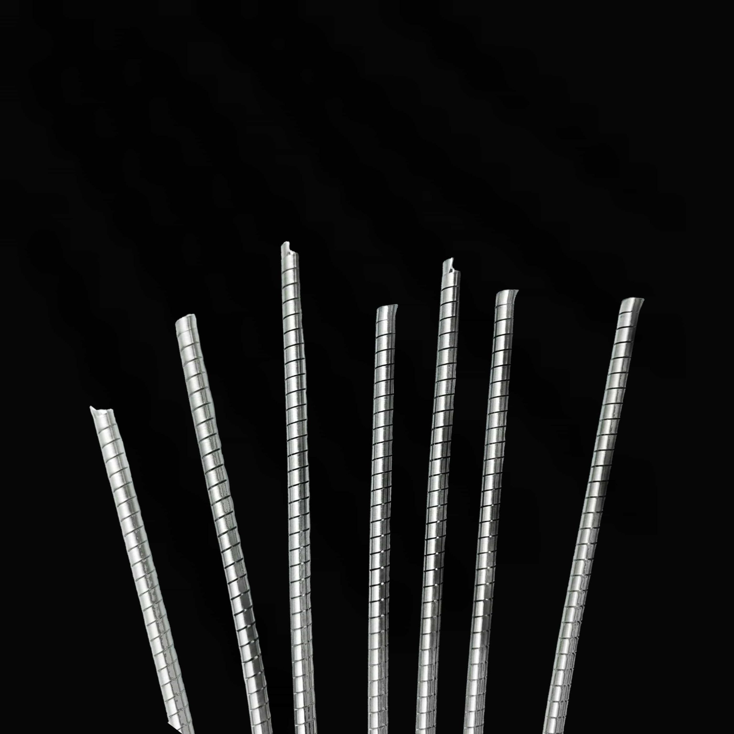
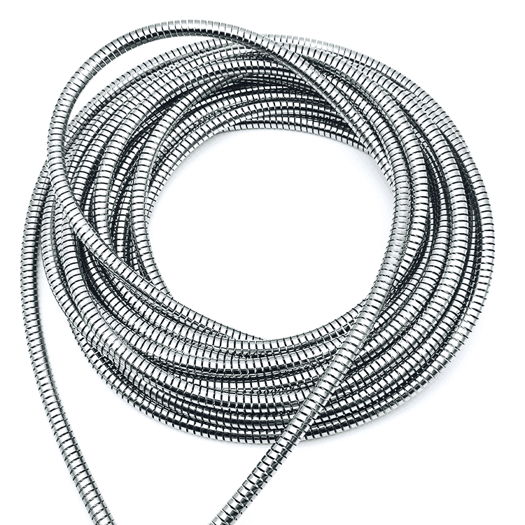
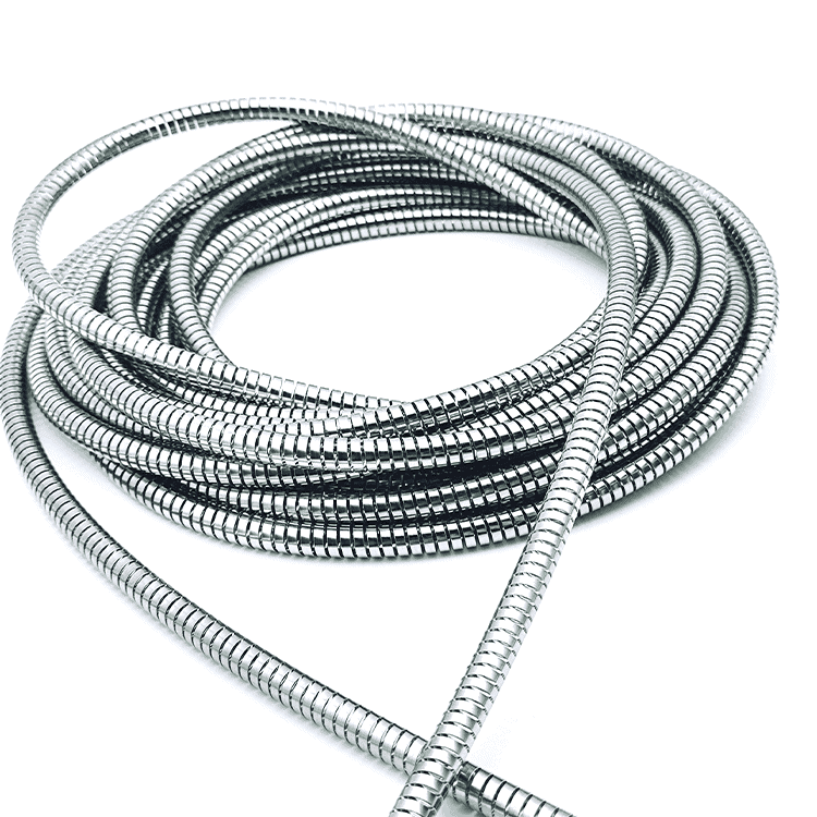
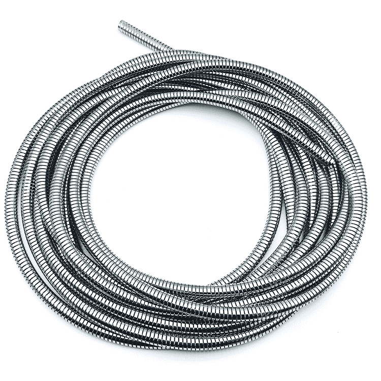
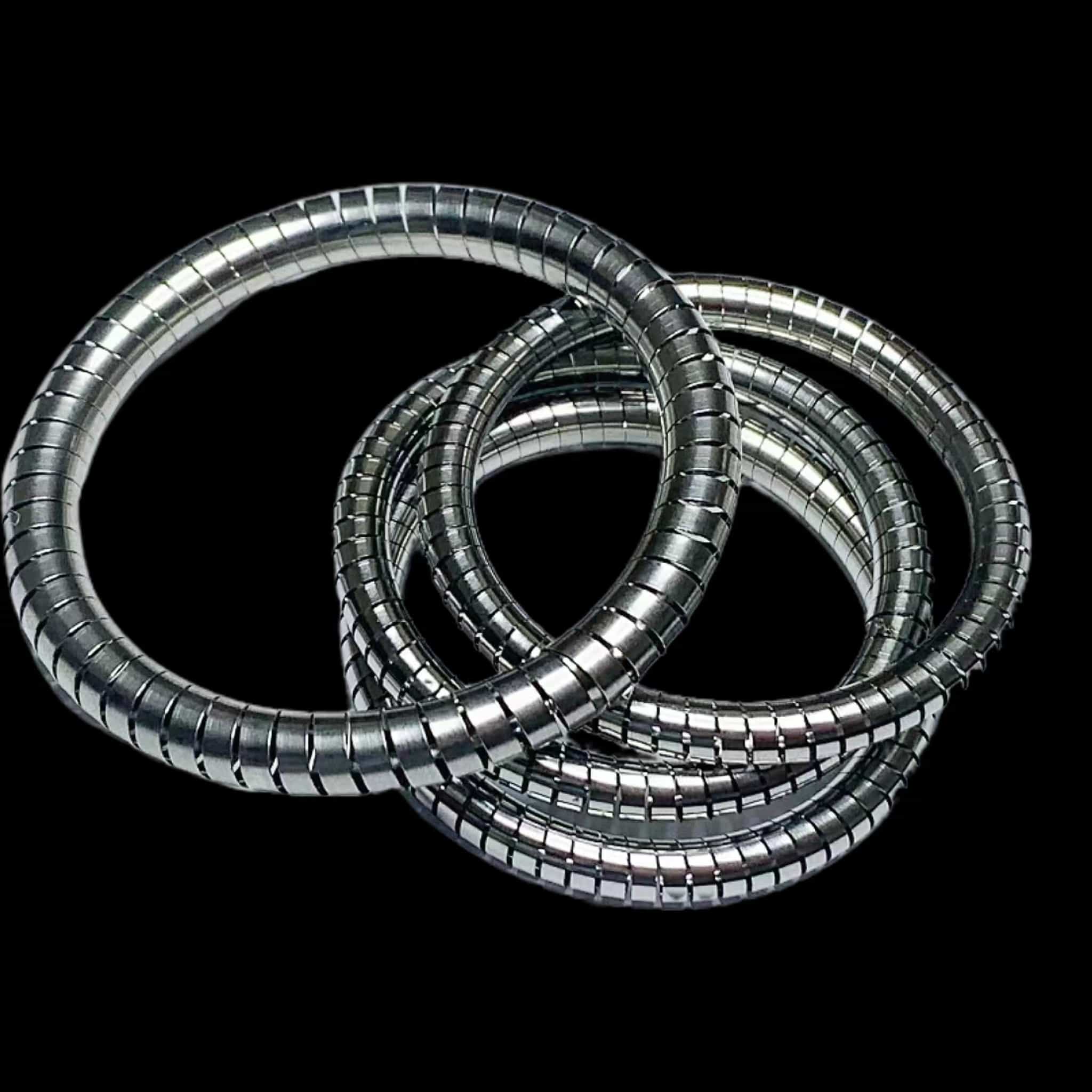
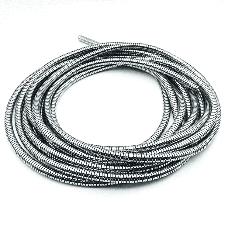
Die EMI-Schraubenfeder (also known as spiral spring or conductive coil spring) is a precision-engineered component designed to provide both mechanical spring force and electromagnetic interference shielding in a single integrated solution. Its unique overlapping coil design creates continuous conductive pathways, ensuring reliable EMI protection across a broad frequency range.
Wesentliche Merkmale:
-
Superior Shielding Effectiveness: Achieves attenuation up to -70 to -80 dB from 1 MHz to 600 MHz
-
Continuous Conductive Contact: Overlapping coil design minimizes gaps and maintains electrical continuity
-
Material Versatility: Available in stainless steel, beryllium copper, phosphor bronze, and exotic alloys (Hastelloy®, Elgiloy®, Inconel®) with various plating options (silver, gold, nickel, tin)
-
Low DC Resistance: Typically 14-30 mΩ per inch for optimal conductivity
-
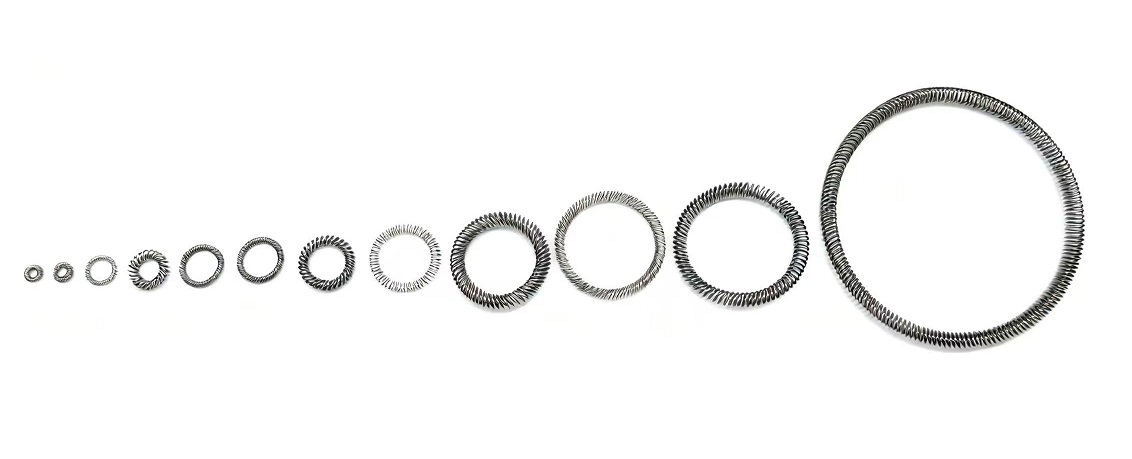
Anpassbares Design: Available in continuous lengths or pre-welded rings; overlap ratio adjustable (20-40%) for performance optimization
Typische Anwendungen: Aerospace avionics, medical devices, electric vehicle battery systems, telecommunications infrastructure, and industrial electronics requiring reliable EMI protection.
Ideal for applications demanding both mechanical resilience and superior electromagnetic shielding performance.
Discover how EMI Helical Springs (spiral springs) provide superior electromagnetic interference shielding. Learn about their design, materials, attenuation performance up to -80 dB, and applications in aerospace, medical, and electronics industries.
Introduction: The Growing Challenge of Electromagnetic Interference
In our increasingly connected world, electromagnetic interference (EMI) has become a pervasive challenge affecting everything from consumer electronics to mission-critical aerospace systems. EMI can result from both unintentional sources—such as electrical wiring, thermal noise, and static discharges—and intentional sources like radio signals, cellular networks, and wireless communication systems .
The elimination of EMI is crucial in electronic system design. Placement of components, along with the use of shielding and filtering, makes it possible to control and reduce interference that can disrupt system function. However, electrical discontinuities in enclosures—such as joints, seams, and gaps—directly affect the frequency and amount of EMI that can breach shielding .
Enter the EMI-Schraubenfeder: a specialized conductive spring design that combines mechanical resilience with exceptional electromagnetic shielding performance. This comprehensive guide explores how these components work, their key advantages, and how to select the right solution for your application.
What is an EMI Helical Spring?
An EMI helical spring (also known as a spiral spring or conductive coil spring) is a precision-engineered component designed to provide both mechanical spring force and electromagnetic interference shielding in a single integrated solution .
Fundamental Design Principles
Unlike standard helical springs that simply store mechanical energy, EMI helical springs are engineered with specific geometries and materials to create continuous conductive pathways. Key design features include:
- Modified spring geometry optimized for consistent electrical contact
- Mehrere Kontaktstellen along the spring circumference
- Ability to maintain seal integrity during dynamic movements
- Adaptability to various shielding configurations
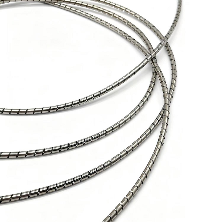
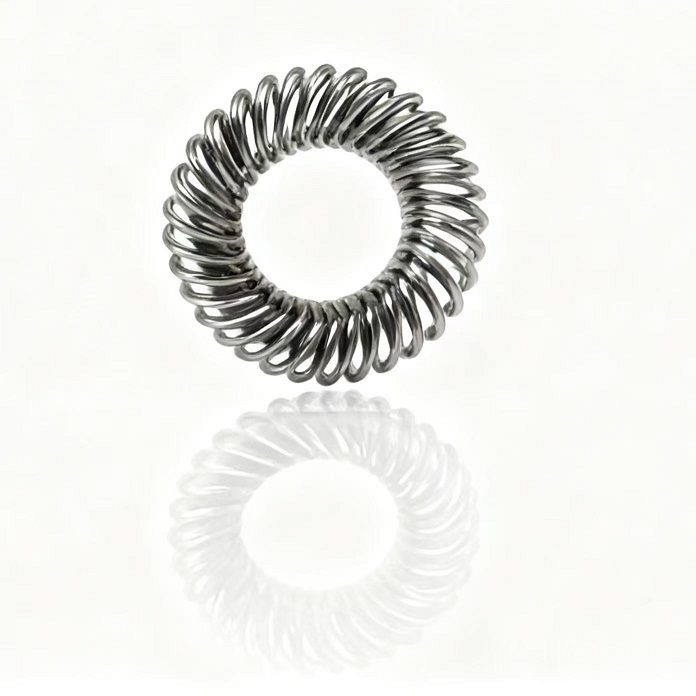
Overlap Helical Coil Design
A particularly effective configuration is the overlap helical coil, where adjacent loops of a conductive ribbon overlap along the width of the ribbon. This design creates a cross-diametric compression spring with superior shielding characteristics .
| Entwurfsparameter | Typical Range | Optimal for Shielding |
|---|---|---|
| Ribbon Width | 0.060-0.300 inches | Wider ribbons increase contact area |
| Ribbon Thickness | 0.003-0.006 inches | Thinner ribbons improve flexibility |
| Overlap Distance | 20-40% of width | 30% overlap provides optimal balance |
| Coil Diameter | <3× ribbon width | Compact designs improve space efficiency |
How EMI Helical Springs Achieve Shielding
The Three Mechanisms of EMI Shielding
EMI/RFI shielding is achieved through three main mechanisms: Reflection, Absorption, and Multiple Reflection .
How Helical Springs Leverage These Mechanisms:
- Reflexion: The conductive material of the helical spring reflects the electric component of electromagnetic waves. Materials with high electrical conductivity—such as silver, copper, and conductive alloys—are most effective for this mechanism .
- Absorption: The magnetic component of EMI is addressed through absorption, which requires materials with high magnetic permeability. Stainless steel alloys and iron-nickel alloys (including mu-metal) excel at this function .
- Multiple Reflection: The helical geometry itself creates multiple reflecting boundaries that scatter electromagnetic waves, further reducing interference through internal reflections .
Continuous Conductive Pathways
The overlapping design of advanced EMI helical springs creates a low-impedance conductive network between components, redirecting EMI away from sensitive electronics. When properly installed, these springs establish:
- Faradayscher Käfig-Effekt: The spring’s continuous conductive loops encapsulate components, blocking external EMI
- Integration der Erdung: Springs maintain electrical continuity to system ground planes, dissipating interference
Materials for EMI Helical Springs
Standard Materials
| Material | Wichtige Eigenschaften | Beste Anwendungen |
|---|---|---|
| Stainless Steel (301, 316) | Good strength, corrosion resistance, magnetic permeability | General industrial, automotive, aerospace |
| Beryllium-Kupfer | Excellent conductivity (22-28% IACS), fatigue resistance | High-conductivity requirements, connectors |
| Phosphor-Bronze | Good corrosion resistance, cost-effective | Industrial environments, consumer electronics |
| Kupfer-Legierungen | High conductivity, easily plated | EMI shielding, grounding applications |
Beschichtungsoptionen
The conductive ribbon can be plated with various metals to enhance performance:
| Plating Material | Nutzen Sie | Typical Application |
|---|---|---|
| Silber | Highest conductivity, corrosion resistance | High-frequency, mission-critical |
| Gold | Excellent conductivity, biocompatible | Medical, aerospace |
| Nickel | Good corrosion resistance, cost-effective | General industrial |
| Zinn | Solderability, cost-effective | Consumer electronics |
Exotic Alloys for Extreme Environments
For applications requiring superior performance in harsh conditions:
| Alloy | Key Characteristics | Anwendungen |
|---|---|---|
| Hastelloy C276 | Superior corrosion resistance | Chemical processing, offshore |
| Elgiloy/Phynox | High strength, extreme temperature resistance | Aerospace, medical implants |
| Inconel | Stabilität bei hohen Temperaturen | Gas turbines, high-temperature processing |
Performance Characteristics and Test Data
Attenuation Performance
EMI helical springs can achieve remarkable shielding effectiveness. Test data from overlapping helical coil designs shows:
- Attenuation: Up to -70 dB to -80 dB reduction in electromagnetic energy passing through shielded spaces
- Frequenzbereich: Substantially constant attenuation from 1 MHz to 600 MHz
- Attenuation Resistance Rating: Not less than 2.0 dB ohms per inch, with premium designs achieving >3.5 dB ohms per inch
Comparative Test Results
| Sample Type | Material | DC Resistance | Compressive Load | Attenuation Performance |
|---|---|---|---|---|
| Overlapping Helical Coil | 301 SS (0.002″×0.125″) | 30.06 mΩ/in | 7.0 lb·ft/in @ 0.015″ | Superior (optimized overlap) |
| Non-Overlapping Helical | 301 SS (0.004″×0.062″) | 14.43 mΩ/in | 9.8 lb·ft/in @ 0.015″ | Standard |
The overlapping design provides significantly better EMI attenuation due to continuous contact and reduced gap formation .
Key Performance Metrics
When evaluating EMI helical springs, consider these critical parameters:
- DC Resistance: Lower resistance indicates better conductivity (typical range: 14-30 mΩ/inch)
- Compressive Load: Affects contact pressure and consistency (5-10 lb·ft/inch typical)
- Attenuation Flatness: Consistency across frequency range
- Contact Redundancy: Multiple contact points ensure reliability under vibration
Branchenübergreifende Anwendungen
Luft- und Raumfahrt und Verteidigung
EMI helical springs are critical in aerospace applications where system failure is not an option:
- Avionik: Shielding flight control systems from radar and communication interference
- Satellitenanschlüsse: Ensuring signal integrity in space-grade applications
- Missile systems: Protecting guidance electronics from electromagnetic pulses
Case Study: In satellite communication systems, gold-plated beryllium copper helical springs provided 40 dB EMI attenuation at 2-18 GHz, maintaining contact under thermal cycling from -65°C to 150°C .
Medizinische Geräte
The medical industry relies on EMI helical springs for:
- MRI-compatible equipment: Non-magnetic materials prevent imaging artifacts
- Implantable devices: Biocompatible materials with reliable shielding
- Diagnostic equipment: Protection of sensitive electronics from interference
Automotive and Electric Vehicles
With the rise of EVs, EMI shielding has become increasingly critical:
- Battery management systems: Protection of sensors from high-voltage inverter interference
- Charging systems: Maintaining signal integrity during power transfer
- Control electronics: Shielding from electromagnetic noise
Case Study: Stainless steel helical springs integrated into EV battery connectors achieved 30 dB reduction in radiated emissions, meeting CISPR 25 compliance standards with 500,000+ cycle durability .
Industrial and Consumer Electronics
- Ausrüstung der Umspannwerke: Protecting sensors in high-voltage environments
- Telekommunikation: Shielding in data centers and communication hardware
- Consumer devices: Compact shielding for smartphones, wearables, and laptops
Installation and Design Considerations
Proper Installation for Optimal Performance
For maximum EMI shielding effectiveness, follow these guidelines:
- Ensure continuous contact: The spring should be compressed to achieve consistent contact with mating surfaces
- Minimize gaps: Opposing ends should be separated by less than 5% of the spring length; welding ends together is recommended for critical applications
- Match groove dimensions: Proper groove design ensures optimal compression and contact force
When to Weld Ends
| Art der Anwendung | End Treatment Recommendation |
|---|---|
| Mission-critical EMI sealing | Weld ends for continuous loop |
| General industrial | May leave small gap (<5%) |
| High-vibration environments | Always weld ends |
| Prototype/testing | Can test with gap, specify welded for production |
Design for Toroidal Applications
For curved installations where the spring forms a torus:
- Inner diameter should be not less than 8 times the coil diameter
- This ensures proper geometry without excessive distortion
EMI Helical Spring vs. Canted Coil Spring
Both helical springs and canted coil springs offer EMI shielding capabilities, but they have distinct characteristics:
| Characteristic | EMI-Schraubenfeder | Kantige Spiralfeder |
|---|---|---|
| Contact Pattern | Continuous spiral contact | Multiple discrete contact points |
| Typical Materials | Stainless steel, copper alloys | Beryllium copper, stainless steel |
| Mechanismus der Abschirmung | Overlapping coils create continuous barrier | Multi-point contact ensures redundancy |
| Beste Anwendungen | Enclosure sealing, gaskets | Connectors, dynamic interfaces |
| Attenuation Range | Up to -80 dB | 86-165 dB (varies by design) |
Both spring types are made from alloy components that offer excellent EMI shielding performance. With correct design and installation, they can block both electric and magnetic components of electromagnetic waves .
Selection Guide: Choosing the Right EMI Helical Spring
Step 1: Define Your Requirements
| Parameter | Questions to Ask |
|---|---|
| Frequenzbereich | What frequencies need shielding? (1 MHz to 600 MHz typical) |
| Attenuation Needed | What dB reduction is required? (-70 dB to -80 dB achievable) |
| Umweltbedingungen | Temperature, humidity, chemical exposure? |
| Mechanical Requirements | Compression force, deflection range, cycle life? |
| Space Constraints | Available groove dimensions, installation envelope? |
Step 2: Select Material
Based on environmental factors :
| Environment | Recommended Material |
|---|---|
| General purpose, cost-sensitive | Stainless steel (301/316) |
| High conductivity needed | Beryllium copper or copper alloy |
| Korrosive Umgebungen | Hastelloy or plated stainless steel |
| High-temperature applications | Inconel or Elgiloy |
| Medical/biocompatible | Gold-plated materials |
Step 3: Choose Design Configuration
- Overlap ratio: 20-40% overlap provides optimal balance of flexibility and shielding
- Coil diameter: Should be less than 3× ribbon width for compact designs
- End treatment: Specify welded ends for critical applications
Step 4: Verify Performance
Request test data including:
- DC resistance measurements
- Attenuation across frequency range
- Compressive load characteristics
- Cycle life test results
Conclusion: The Versatile Choice for EMI Protection
EMI Helical Springs represent a proven, versatile solution for electromagnetic interference shielding across virtually every industry. Their unique combination of continuous conductive contact, mechanical resilience, and design flexibility makes them indispensable in applications where reliable shielding is critical .
From aerospace systems operating in extreme environments to medical devices requiring biocompatibility, and from electric vehicles to telecommunications infrastructure, EMI helical springs deliver the performance and reliability that modern electronics demand .
When properly selected and installed, these components provide:
- Superior attenuation: Up to -80 dB reduction in electromagnetic interference
- Broad frequency coverage: Consistent performance from 1 MHz to 600 MHz
- Mechanical integrity: Maintains shielding under vibration and dynamic conditions
- Long-term reliability: Proven performance in mission-critical applications
Das könnte Ihnen auch gefallen
-
 Kundenspezifische O-Ring-Dichtungen: Der ultimative Leitfaden für Materialien, Größen und Herstellung
RF/EMI-Abschirmung Spiralförmige Dichtung
Kundenspezifische O-Ring-Dichtungen
O-rings are among the most widely used sealing elements in hydraulic, pneumatic, automotive, aerospace, and industrial systems worldwide. Despite their simple donut-shaped appearance, these components play a critical role in preventing fluid and gas leakage under diverse operating conditions . For......
-
Was ist ein Quick Shield aus Edelstahl? Eigenschaften, Vorteile und Anwendungen von HANDA Quick Shield
RF/EMI-Abschirmung Spiralförmige Dichtung
Handa Schnelles Schutzschild
Erfahren Sie, was ein Quick Shield aus Edelstahl ist, wie es funktioniert und warum HANDA Quick Shield eine zuverlässige EMI-Abschirmung für Elektronik-, Luft- und Raumfahrt- sowie Industrieanwendungen bietet. Entdecken Sie die Merkmale, Vorteile und die wichtigsten Designüberlegungen. Elektronische Geräte werden immer kleiner, schneller, ......
-
EMI-Abschirmungsdichtung Muster anfordern | Testen, bevor Sie spezifizieren
RF/EMI-Abschirmung Spiralförmige Dichtung
Handa Spiralförmige Abschirmung
EMI Shielding Gasket Sample Request | Test Before You Specify Meta Description Senden Sie eine EMI Shielding Gasket Sample Request, um Materialleistung, Passform und Abschirmungseffektivität vor der endgültigen Spezifikation in kritischen Anwendungen zu bewerten. EMI-Abschirmung Dichtungsmuster anfordern: Eine praktische......
-
Kundenspezifisch gebogene Spiralfeder: Designüberlegungen und Herstellungsverfahren
Fingerabdrücke
Rechtwinklige Abschirmung Fingerstrip
Kundenspezifische Schraubenfedern bieten maßgeschneiderte Kraft, Einfederung und Haltbarkeit für anspruchsvolle Anwendungen. Erfahren Sie mehr über die wichtigsten Konstruktionsüberlegungen, Werkstoffe, Herstellungsverfahren und Qualitätskontrollen für kundenspezifische Schraubenfederlösungen. Einführung In den heutigen mechanischen und elektrischen Hochleistungssystemen werden oft Standardkomponenten......
-
Kraftverlust bei kantigen Spiralfedern: Ursachen und Lösungen
Fingerabdrücke
Rechtwinklige Abschirmung Fingerstrip
Kraftverlust bei kantigen Schraubenfedern erklärt. Erfahren Sie mehr über die Ursachen, die Auswirkungen auf die Leistung und bewährte technische Lösungen zur Gewährleistung einer langfristigen Zuverlässigkeit der Feder. Einführung Geneigte Schraubenfedern sind weithin für ihre Fähigkeit bekannt, eine nahezu konstante Kraft über einen weiten ......